Call Us 24/7
+91 6357173693
Send Us Mail
business@imacengineering.com
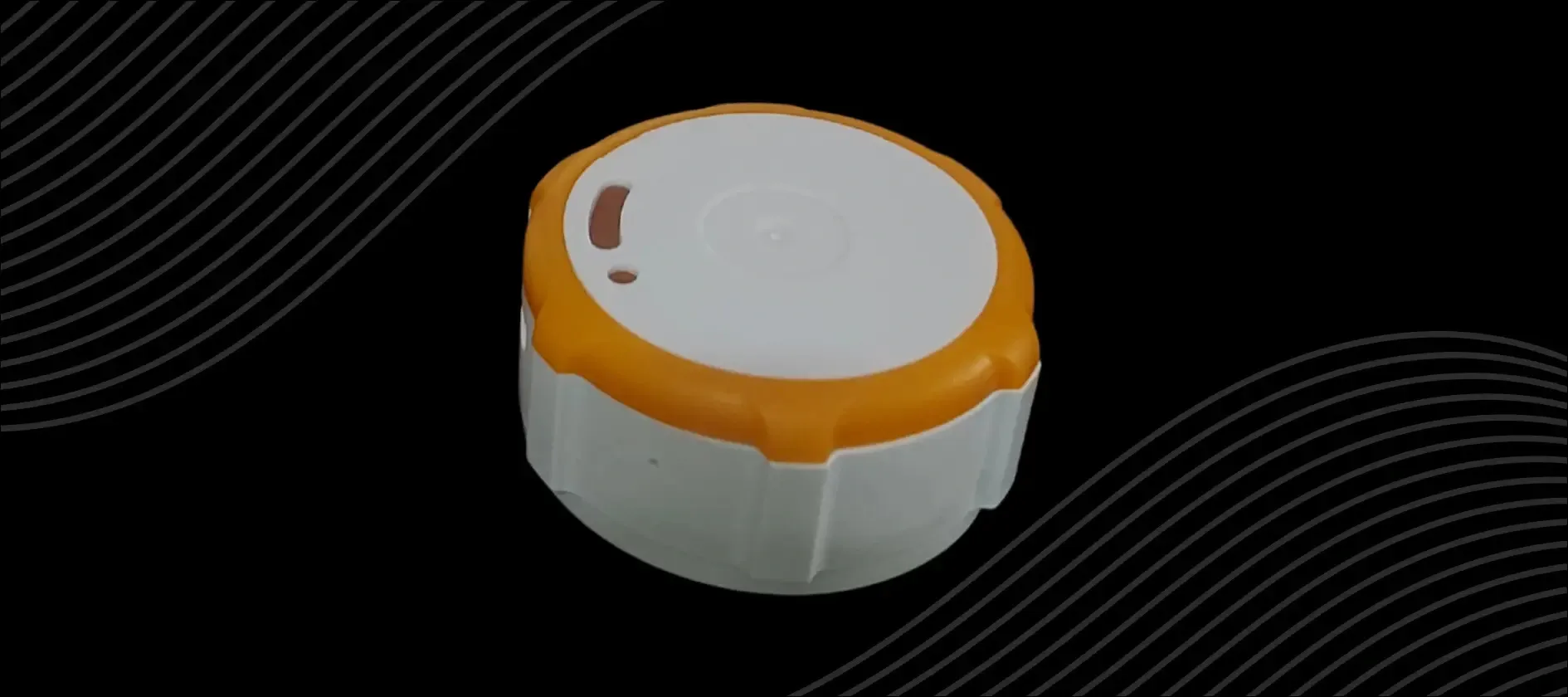
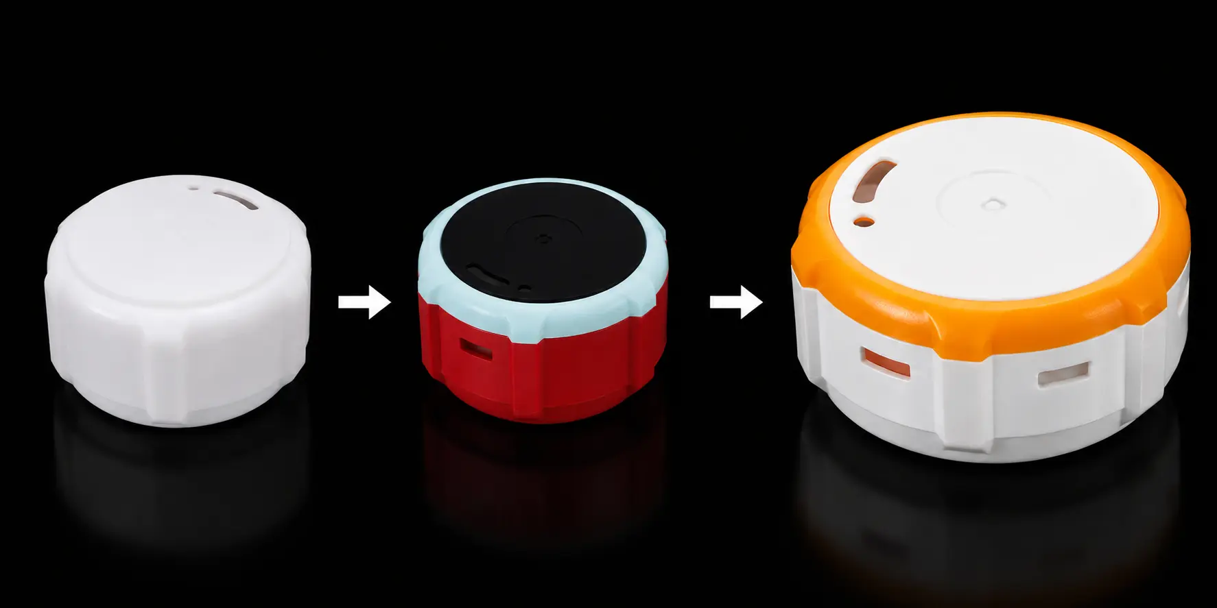
This smart pill cap redesign replaced inconsistent glue assembly with a reliable snap-fit enclosure, clearer LED indication, secure sealing, and visible tamper evidence.
This case study covers iMAC Design and Engineering Services’ mechanical enclosure design work on an intelligent pill cap — a SIM-based cellular IoT device that alerts patients and doctors when medication doses are missed.
The project was a redesign. The existing glue-based assembly had reliability and consistency problems, and the product needed to move to snap-fit construction without compromising seal integrity, PCB protection, or the optical clarity of its dual-LED indicator. iMAC’s design scope covered snap-fit joint engineering, the sealing mechanism, light pipe design, tamper-evident feature, material selection, tolerance control, and prototype validation through FEA and simulation.
| Product | Smart Pill Cap – SIM-based cellular IoT device |
|---|---|
| Industry | Medical IoT / Healthcare |
| Services | Product Design & Development, Plastic Enclosure Engineering |
| Stage | Redesign – glue assembly to snap-fit construction |
| Design Scope | Snap-fit joints, sealing, light pipe, tamper feature, material and tolerance spec |
The original enclosure had four distinct problems, all of which needed to be resolved together:
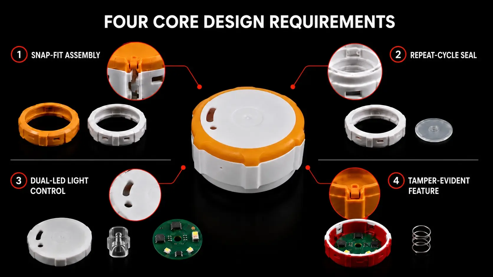
The brief required a complete mechanical redesign of the pill cap enclosure with four non-negotiable outcomes.
Assembly had to move from glue to snap-fit — faster, more consistent, and repeatable at production volume. The seal had to hold reliably through repeated use cycles. The visual indicator, a single light pipe showing two distinct LED states, had to be optically clean with no bleed between channels. The product also needed a tamper-evident feature that breaks visibly when the cap is opened improperly, without the snap geometry putting excessive force on the PCB underneath.
All of this had to work within injection molding constraints — managing shrink marks, mold complexity, and dimensional tolerances that affect both fit and function.
Moving from glue to snap-fit without sacrificing seal integrity: Snap-fits introduce their own set of problems. The mold geometry required to produce reliable snap arms carries a risk of sink marks on visible surfaces. Snap arms engineered for high retention force can compress the PCB during assembly. And replacing glue does not eliminate the sealing requirement — the cap still needs to prevent moisture ingress around the seal disc, which had already failed under repeated cycling in the original design.
Controlling dual-LED light bleed through a single light pipe: The cap uses one light pipe to indicate two distinct LED states. Without precise internal geometry — reflective surfaces, channel separation, controlled light paths — the two channels bleed into each other and the indicator becomes ambiguous. Getting this right inside a compact enclosure, with the light pipe held in alignment under snap-lock tabs, required optical and mechanical design to work together.
Engineering a tamper feature that breaks cleanly without damaging the PCB: A sacrificial snap that breaks on intrusion requires careful geometry tuning. The snap arm needs enough retention to survive normal handling but must break at a predictable, low force when someone opens the cap improperly. Too stiff and it risks PCB damage during removal. Too weak and it breaks in normal use or shipping. The feature also could not introduce additional leak paths or complicate the assembly sequence.
Snap-fit joint redesign: fewer, larger, better
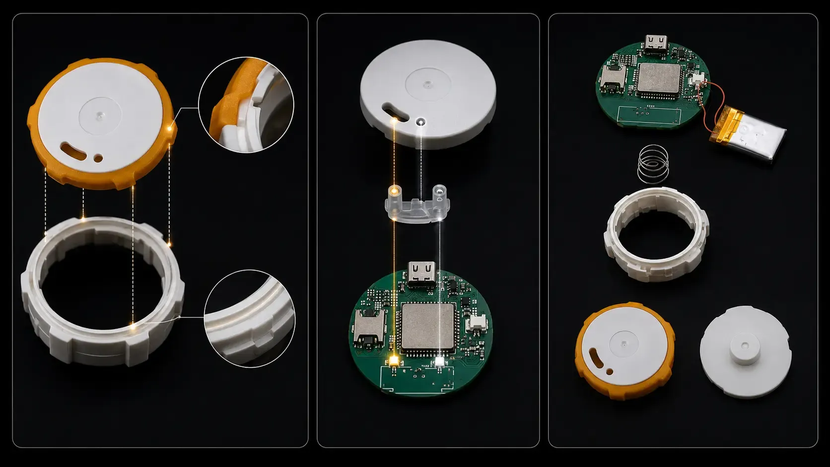
The team replaced the glued assembly with snap-fit joints, increasing individual snap size while reducing total count. Fewer, larger snaps are more robust and assemble more consistently than many small ones. Each snap arm was geometrically tuned with a tapered profile, fillet radii, lead-in angles, and a minimum width of 5 mm to balance retention force against PCB compression risk. The assembly clicks together repeatably without over-stressing the electronics underneath.
Rib-supported cantilever seal
The team redesigned the sealing mechanism as a rib-supported cantilever snap-lock. The cantilever ribs serve two functions: they prevent sink marks in the mold by providing material support at the snap geometry, and they maintain consistent sealing force across the contact surface. Tapers and fillets on the cantilever reduce stress concentrators that cause fatigue failure under repeated cycling — which is what caused the original seal disc to fail.
Single light pipe with internal reflective channels
The team designed a single light pipe with internal reflective surfaces that guide the two LEDs independently through separate optical paths. Snap-lock tabs hold the light pipe in alignment within the housing so the channels stay registered to their respective LEDs. This eliminates the scatter and bleed that made the original dual-LED indicator unclear.
Sacrificial tamper-evident snap
The team engineered a dedicated sacrificial snap feature to break visibly when someone opens the cap improperly. Geometry tuning — taper, width, lead-in angles, fillets — sets the failure force at a level well below the threshold that would stress the PCB. The feature is visually obvious when broken, providing clear tamper evidence, and its geometry sits outside the main seal path so it does not create a leak route when it fails.
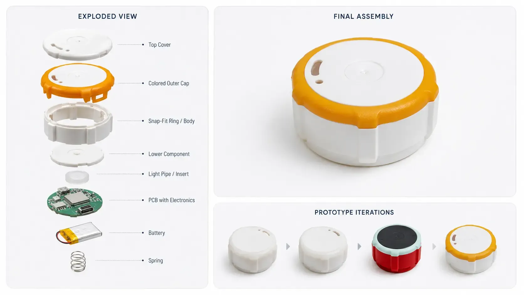
Prototype validation
Prototype cycles included FEA and simulation to validate insertion and extraction forces, stress distribution across snap arms, and sealing performance.
| Design Area | Before | After |
|---|---|---|
| Assembly method | Glue — slow, inconsistent | Snap-fit — fast, repeatable |
| Seal | Disc seal, failed under repeated use | Rib-supported cantilever snap-lock |
| LED indication | Dual LEDs with light bleed and scatter | Single light pipe, independent channels, no bleed |
| Tamper evidence | None | Sacrificial snap — breaks visibly, PCB safe |
| Sink marks | Risk from snap mold geometry | Eliminated by cantilever rib support |
| PCB compression | Risk from over-retention | Controlled by snap arm geometry tuning |
The redesigned pill cap enclosure resolved every problem in the original design.
Fewer, larger snap-fits replaced glue, cutting material cost, reducing assembly time, and delivering consistent results at production volume. The rib-supported cantilever seal held through repeated cycle testing with no failures and no sink marks. The light pipe clearly distinguishes the two LED states with minimal optical scatter. The tamper-evident snap breaks at a controlled, low force, visibly indicating intrusion without putting stress on the PCB.
The product meets client specifications and production standards for a snap-fit injection-molded medical IoT enclosure, with snap-fit durability and mold reliability verified through prototype cycles.
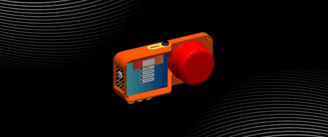
See how iMAC developed a modular fire-detection and suppression system for harsh mining conditions using multi-sensor monitoring and protected electronics.
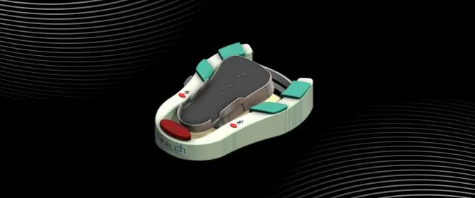
See how iMAC transformed a legacy surgical foot pedal with simplified mechanics, ergonomic form, tactile controls, and non-contact position sensing.

A comprehensive medical device redesign focused on structural refinement, component integration, and improved usability for real clinical environments.
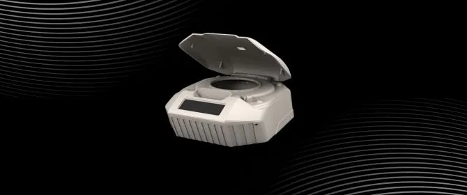
See how iMAC refreshed an existing centrifuge enclosure with an automotive-inspired design that preserved the core mechanics and supported low-cost injection molding.