

Tooling Design & Development for Product Manufacturing
Explore how tooling design supports product manufacturing, what affects cost and lead time, and how to avoid rework before full-scale production.
Explore how tooling design supports product manufacturing, what affects cost and lead time, and how to avoid rework before full-scale production.
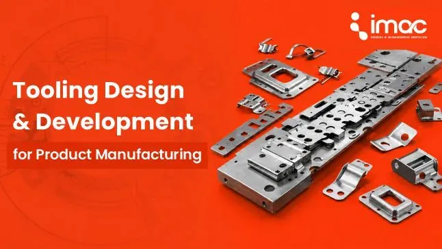
A product that works as a prototype does not automatically work as a manufactured product. The prototype proves the idea. Tooling proves whether that idea can be produced repeatedly at the required quality, volume, and cost.
Tooling design and development is the stage where a validated product becomes a repeatable manufacturing process through the molds, dies, jigs, fixtures, and gauges used to shape, hold, assemble, and inspect its parts.
Starting tooling too early can lock unresolved geometry, materials, tolerances, or assembly problems into an expensive physical tool. This guide explains when a product is ready for tooling, how the tooling process works, what affects cost and lead time, and which mistakes commonly cause rework and production delays.
Tooling design and development is the process of engineering, building, testing, and approving the molds, dies, jigs, fixtures, and gauges used to manufacture a product. It sits between prototyping and full production. Soft tooling supports low-volume builds, bridge tooling supports early commercial production, and production tooling supports stable manufacturing at scale. Cost and lead time depend on complexity, material, tolerance, expected life, and trial requirements.
Tooling design and development covers the product-specific equipment used to shape, hold, assemble, or inspect parts during manufacturing.
The purpose of tooling is to make parts consistently, with repeatable dimensions, predictable cycle times, safe operation, and controlled wear.
Tooling also connects product engineering with manufacturing engineering. Product geometry influences parting lines, draft angles, clamping points, ejection methods, cooling layouts, and inspection datums. Tooling decisions should therefore begin during design for manufacturing, not after product design is complete.
Think of tooling design as the blueprint stage and tooling development as the build-and-prove stage. Initial tool design happens in CAD and simulation software before fabrication, while later trials may lead to further design refinements.
Development happens on the shop floor, where the tool is machined, assembled, tested, and adjusted until real parts match the design intent. A tool can be perfectly designed and still need several rounds of development before it's production-ready.
Depending on the manufacturing process, a hardware product may require molds, dies, jigs, fixtures, or inspection gauges. Injection molds produce plastic or elastomer parts, while dies, including progressive dies for multi-step forming operations, cut, bend, or form sheet metal. Jigs guide tools or operators, and fixtures hold parts in position during machining, welding, assembly, or inspection.
A single product may need an injection mold for its enclosure, a forming die for a metal bracket, an assembly fixture to position the components, and gauges to verify critical dimensions. These tools should work together as part of one production system.
Soft tooling generally uses lower-cost materials or simplified construction. It suits pilot production, low-volume manufacturing, design validation, and early market testing because it can usually be produced and modified faster. Additively manufactured (3D-printed) jigs and fixtures are increasingly used at this stage too, since they can be produced in days rather than weeks when a design is still likely to change.
Bridge tooling supports the period between prototypes and stable high-volume production. It can help a team supply early customers or collect field feedback before committing to a long-life tool.
Production tooling uses more durable materials and robust construction to support higher volumes, longer tool life, tighter process control, and consistent part quality.
The right choice depends not only on volume, but also on design maturity, tolerances, material behavior, expected product life, maintenance requirements, and the likelihood of future changes.
Choosing a tooling tier based only on forecast volume can lead to the wrong investment. iMAC recommends considering design stability, expected revisions, validation needs, tool life, and launch timing before selecting soft, bridge, or production tooling.
Is your product ready for long-life tooling, or does it still need a flexible production route?
A product should move to tooling only after the team has confirmed that it works and can be manufactured consistently. A prototype may prove fit and function, but it may not reflect production materials, tolerances, draft angles, assembly methods, or cycle-time limits.
Starting too early can lock unresolved issues into an expensive tool. The decision should come from completed engineering work, not only from pressure to meet a launch date.
Before tooling begins, the team should approve a controlled CAD revision and matching manufacturing drawings. Part geometry, materials, finishes, critical dimensions, tolerances, purchased components, and assembly interfaces should no longer be open decisions.
Expected production volume should also be clear because it influences the tool material, number of cavities, cooling design, cycle time, and expected tool life.
A design freeze does not prevent future changes. It simply means the team understands that later revisions may affect cost, lead time, and validation.
Functional testing, fit checks, assembly trials, DFM findings, tolerance analysis, and material decisions should be reviewed before the tool is released.
The team should also define how trial parts will be approved. This may include dimensional limits, cosmetic standards, functional performance, leakage tests, force requirements, or electrical checks.
For medical device design and safety-critical and regulated products, design changes made after tooling begins may require additional risk assessment, verification, validation, and documentation.
Frequent CAD changes are one of the clearest warning signs. Unresolved test failures, undecided materials, missing tolerances, incomplete drawings, or pending supplier decisions also show that the design is not ready.
Another warning sign is expecting the toolmaker to solve unfinished product-engineering problems during fabrication. Tooling can refine the manufacturing process, but it cannot compensate for an unstable design.
A deadline may create urgency, but it does not prove tooling readiness.
Once a design is frozen and validated, the tooling process itself follows a fairly consistent sequence, though the details shift depending on whether you're molding plastic, stamping metal, or casting.
The tooling team needs released 3D CAD files, controlled drawings with GD&T, material and finish specifications, target production volume, cycle-time expectations, machine compatibility details, tool-life requirements, and sample approval criteria.
These inputs help the toolmaker understand how the part should look, function, and perform in production. Missing or unclear information often leads to assumptions, inaccurate quotations, design changes, and avoidable delays later.
Engineers convert product requirements into a tool concept, select the material, define wear areas, and design features such as cavities, punches, dies, sliders, cooling channels, ejectors, nests, locators, and clamps.
Toolmakers fabricate and inspect each component before assembly. They then complete bench checks and dry runs where possible.
Before the first production trial, the team confirms machine settings, raw material, process parameters, measurement methods, and sample quantities. This helps separate tool defects from process-setting problems.
T0, T1, and T2 refer to different stages of injection mold trials, although suppliers may use the terms slightly differently.
T0 is usually an internal toolmaker trial. It confirms that the mold opens, closes, fills, cools, and ejects the part safely. The focus is basic tool operation rather than final part quality.
T1 produces the first formal samples for engineering review. The team checks dimensions, appearance, fit, function, filling, warpage, flash, sink marks, short shots, weld lines, and ejection performance.
After T1, the toolmaker completes the agreed corrections. T2 samples are then used to verify whether those changes have resolved the identified issues. Further trials may be needed if the parts still do not meet the approved requirements.
The trial number alone does not approve the tool. Inspection and functional evidence must support the final decision.
Are your tooling samples supported by inspection and functional test results?
The team compares samples against released drawings and quality standards. Inspection may include dimensional reports, first-article inspection, material verification, cosmetic review, fit checks, assembly trials, and functional testing.
Critical dimensions may require a coordinate measuring machine, gauges, optical inspection, or capability studies.
Approval should record the accepted sample, tool revision, process settings, material grade, inspection results, and any temporary deviations. This creates a controlled baseline for production.
Tooling cost reflects engineering effort, fabrication complexity, material, accuracy, expected life, and qualification requirements.
A single-cavity aluminum mold normally requires less investment than a hardened multi-cavity steel mold with side actions, complex cooling, tight tolerances, and demanding textures. Similar principles apply to dies, jigs, fixtures, and gauges.
Lead time also depends on design readiness. Stable inputs, clear acceptance criteria, and prompt decisions allow suppliers to work efficiently. Late geometry changes and delayed feedback extend the schedule.
Teams should compare quotations by scope, not only total price. A low quotation may exclude simulation, sampling, inspection reports, spare inserts, maintenance, or modifications. For small manufacturers working with tighter budgets, starting with soft or bridge tooling is usually the more affordable route into production, since it defers the larger investment until volume and design stability justify it.
Common cost drivers include large part size, complex geometry, undercuts, sliders, multiple cavities, hardened materials, precision fits, fine textures, complex cooling, replaceable inserts, and high tool-life targets.
Tight tolerances increase machining and inspection effort. Qualification activities such as first-article inspection, capability studies, documentation, or validation runs can also extend the schedule.
Bridge tooling makes sense when the design is relatively stable but long-term demand or production volume is still uncertain.
It can support an early launch, customer trials, investor milestones, or limited production while the team gathers real-world data. It reduces the risk of committing to an expensive long-life tool too early.
However, bridge tooling is not always cheaper across the full program. If demand rises quickly, the business may pay for both bridge and production tools. The decision should compare launch timing, forecast volume, likely revisions, unit economics, and the cost of delay.
Starting tooling before the design is frozen is one of the most common causes of rework. Even a small geometry change can affect cavities, inserts, parting lines, cooling channels, fixtures, or inspection gauges.
Other mistakes include missing draft, unrealistic tolerances, poor datum selection, weak ejection planning, insufficient cooling, inaccessible fasteners, and failure to consider assembly variation.
Teams also create delays when they approve samples visually without checking dimensions and function. A part can look acceptable while still causing assembly or reliability problems.
Poor revision control creates another risk. If the toolmaker, product team, and manufacturer use different CAD revisions, corrections may target the wrong requirement.
Also Read: How to Reduce Product Development Risk Before Spending on Tooling
A capable partner or vendor should understand the selected manufacturing process, whether that's molding, stamping, casting, or precision machining, and how it affects product design.
Review the partner's DFM capability, tool design resources, fabrication methods, inspection equipment, trial capacity, documentation, change-control process, maintenance support, and production experience.
Confirm what the quotation includes. Clarify responsibility for design, simulation, samples, inspection reports, corrections, spare parts, storage, maintenance, and transfer.
The agreement should state who owns the tool, CAD data, inserts, and modification rights. Strong partners communicate problems early and explain the trade-offs behind their recommendations.
The wrong tooling partner can lead to repeated corrections, delays, and ownership disputes.
iMAC Design & Engineering Services, based in Ahmedabad, India, structures every project around a 7-stage process:
Design Research → Innovation & IP Strategy → Product Design → Engineering → Prototyping → Tooling → Manufacturing
This position matters because tooling should receive validated inputs from product design, engineering, and prototyping. It should then produce approved tools, samples, inspection evidence, and process knowledge for manufacturing.
The stages may overlap. Tooling engineers can provide DFM feedback before prototype validation is complete, while manufacturing engineers can review fixtures and inspection methods during tool development.
iMAC applies this structured approach across 140+ projects under ISO 9001:2015 and ISO 13485:2016 quality systems. By treating tooling as part of product development rather than an isolated purchase, teams can preserve design intent and reduce gaps as the product moves into production. If you are preparing a validated product for tooling and manufacturing, contact iMAC Engineering to discuss the next steps.

 Download Brochure


