Reverse Engineering Process: Explained Step-by-Step
This guide explains the reverse engineering process step by step, risks, prevention strategies, and types.
This guide explains the reverse engineering process step by step, risks, prevention strategies, and types.
The reverse engineering process is used when design intent exists physically, but the digital design data does not. That usually shows up as a part you must keep producing, a component that needs inspection ready documentation, or a product that must be updated without breaking fit, function, or compliance.
Reverse engineering rebuilds reliable CAD and engineering references from an existing component so it can be manufactured, validated, or improved with confidence!
This blog explains how reverse engineering works, how each stage protects accuracy, and where engineering control is established before manufacturing begins.
✓ A successful reverse engineering process starts by defining a clear goal that guides every subsequent step.
✓ Clear step sequencing prevents costly rework and production failure.
✓ Validation is the most critical and most skipped stage.
✓ Reverse engineering restores design control when CAD is missing.
✓ Different project goals require different reverse engineering methodologies.
✓ Strong workflows can easily convert physical parts into long-term digital assets.
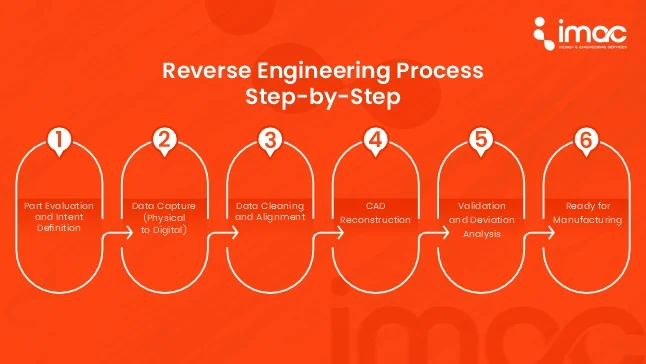
Understanding reverse engineering process follows a defined workflow: part evaluation, data capture, CAD reconstruction, validation, and manufacturing readiness. Each step reduces risk and improves accuracy before the part is reused or redesigned.
1. Part Evaluation and Intent Definition
Before scanning or modeling, engineers study the part. Materials, wear patterns, tolerances, and functional surfaces are identified. This step decides what must be exact and what can be interpreted. Skipping this leads to perfect geometry with zero usability.
2. Data Capture (Physical to Digital)
The component is captured using appropriate measurement methods, contact or non-contact, based on accuracy needs and surface complexity. This step defines the quality of everything that follows in the reverse engineering workflow.
3. Data Cleaning and Alignment
Raw scan data is not design-ready. Noise, overlaps, and inconsistencies are cleaned. Reference planes and symmetry are established. This is where engineering judgment matters more than software.
4. CAD Reconstruction
Surfaces and solids are rebuilt to match functional intent, not just shape. Features are constrained, dimensions are rationalized, and manufacturability is considered. This is the core of the reverse engineering methodology.
5. Validation and Deviation Analysis
The rebuilt CAD is compared against the original part. Deviations are measured and accepted only if they meet functional limits. This step protects downstream manufacturing.
6. Ready for Manufacturing
Final CAD, drawings, and documentation are prepared for tooling, machining, or production. At this point, the part is no longer “reverse engineered” it is engineered again.
The reverse engineering steps are a loop of capture, create, and validate, ensuring the output is not just a shape, but a functional, manufacturable asset.
Most failures in reverse engineering come from unclear intent, poor validation, or over-reliance on tools. A structured process prevents these errors before they become production problems.
| What can go wrong | How the structured process prevents it |
| Inaccurate or incomplete data capture | The planning phase selects the optimal tools used in reverse engineering (e.g., a high-res scanner for complex contours, a CMM for prismatic features). Validation steps compare data to the source. |
| Misinterpreting data intent | The process forces analysis beyond shape. Why is this rib here? Why this material? The reverse engineering methodology includes functional testing and material analysis to deduce intent. |
| Creating an unmanufacturable model | By involving manufacturing expertise early and validating the model for standard toolpaths and tolerances, the workflow ensures the digital output is ready for production. |
| Legal & IP infringement | The initial goal-definition stage is where ethical and legal boundaries are set. A professional process is scoped for legitimate purposes like repair, interoperability, or documented legacy part recreation, avoiding patent or copyright violation. |
The type of reverse engineering depends on whether the goal is replication, improvement, or analysis.
1. Geometric Reverse Engineering
This type focuses on capturing the exact shape and dimensions of an existing part. It is used when form, fit, and assembly compatibility are critical.
Used when:
✓ CAD data is missing or unreliable
✓ Replacement parts must match existing assemblies
✓ Tooling or fixtures depend on precise geometry
Outcome: Manufacturable CAD that matches the physical part within defined tolerances.
2. Functional Reverse Engineering
Here, geometry alone is not enough. Engineers study how the part works, where it carries load, how it interfaces, and why features exist.
Used when:
✓ Performance matters more than shape accuracy
✓ Failures or wear patterns need explanation
✓ Design intent must be reconstructed, not copied
Outcome: CAD that reflects functional logic, not just scanned surfaces.
3. Manufacturing Reverse Engineering
This type rebuilds the design with production feasibility as the priority. Features are simplified, tolerances rationalized, and materials reconsidered.
Used when:
✓ Original manufacturing methods are unknown
✓ Suppliers or processes have changed
✓ Cost, yield, or scalability must improve
Outcome: A production-ready design aligned with modern manufacturing methods.
4. Material Based Reverse Engineering
This approach analyzes material composition, treatments, and finishes alongside geometry.
Used when:
✓ Parts fail unexpectedly
✓ Performance varies between batches
✓ Compliance or durability is critical
Outcome: Design and material specifications that explain real-world behavior.
5. Validation Reverse Engineering
In some projects, reverse engineering is done primarily to verify accuracy, not redesign.
Used when:
✓ Legacy parts must be certified or audited
✓ Documentation is needed for quality or compliance
✓ Engineering confidence must be re-established
Outcome: Verified CAD and reports that support inspection, testing, or certification.
6. Competitive Reverse Engineering
This approach is used to benchmark performance, cost, durability, and manufacturability. The goal is to identify what works, what adds unnecessary complexity, and where improvements are possible without violating intellectual property boundaries.
Used when :
✓ Evaluate alternative design strategies
✓ Improve product performance or reduce cost
✓ Avoid repeating known design limitations
✓ Make informed redesign decisions based on real-world products
The outcome is a clear direction for better product decisions grounded in how existing solutions actually perform.
Each type follows the same reverse engineering process, but the priority changes - shape, function, manufacturability, or validation. Choosing the wrong type leads to perfect models that fail in production.
At iMAC engineering, reverse engineering is always selected based on what the part must achieve next, not on how it was originally made.
The reverse engineering process is a controlled engineering recovery method used when design data is missing, but performance cannot fail.
Want to see how this process applies to your specific challenge? iMAC Engineering works on reverse engineering projects where accuracy, validation, and manufacturability matter. So let's talk about your project.
The reverse engineering process converts a physical part into validated digital design data through inspection, data capture, CAD reconstruction, and comparison. The goal is not copying shape, but restoring usable engineering intent for manufacturing or redesign.
The key steps involved in reverse engineering include part evaluation, measurement or scanning, data cleanup, CAD rebuilding, deviation analysis, and manufacturing documentation.
No. Reverse engineering tools only capture or process data. Accuracy depends on how engineers define intent, manage tolerances, and validate results. Tools support the process; they do not replace engineering judgment.
Reverse engineering is ideal when a part already works but lacks reliable documentation. Redesign is chosen when performance changes are required. Many projects start with reverse engineering and transition into redesign.
Aerospace, automotive, medical devices, industrial manufacturing, and consumer products frequently use reverse engineering workflows to manage legacy parts, supplier changes, and undocumented design evolution.